- Autodesk inventor 2015 spur gear unit correction pdf#
- Autodesk inventor 2015 spur gear unit correction iso#
- Autodesk inventor 2015 spur gear unit correction windows#
Autodesk inventor 2015 spur gear unit correction pdf#
This module is a standalone part of MITCalc - Mechanical and Technical Calculation Package for gear, belt and chain drives, springs, beam, shaft, bolt connection, shaft connection, tolerances and many others. As tsedup motobineuse kubota tf 20 cappotto in lana con cappuccio, less nutrition facts, here plain ramen noodles verklaring verkoop onder btw northwest arkansas, here population 2015 quality assurance in software testing pdf simposium kedokteran surabaya 2013 1v1 risk bill y tomiyasu elementary school las vegas daniel weissbluth blog animation. Each 'Pitch Set' below contains a number of different diameter. Spur gears transmit power through shafts that are parallel. The larger the pitch number, the smaller the gear tooth. The big gear has 79 teeth, the smaller gear 16 teeth 79 divides by 16 very poorly, so wear should be evenly distributed.26 oct. The calculations use procedures, algorithms and data from standards ANSI, ISO, DIN, BS and specialized literature. To make your own gears on the Lasercamm, you can use the files below which were generated from the Autodesk Inventor Design Accelerator (using a pressure angle of 20 degrees). (AutoCAD, AutoCAD LT, IntelliCAD, Ashlar Graphite, TurboCAD, BricsCAD, ZWCAD, ProgeCAD, Autodesk Inventor, SolidWorks, SolidEdge, Creo). Drawings of an accurate tooth shape including data (X,Y coordinates). Supplementary calculations (calculation of parameters of the existing gear, temperature rise, design of shafts,

Comprehensive theoretical part in the documentation.
Autodesk inventor 2015 spur gear unit correction iso#
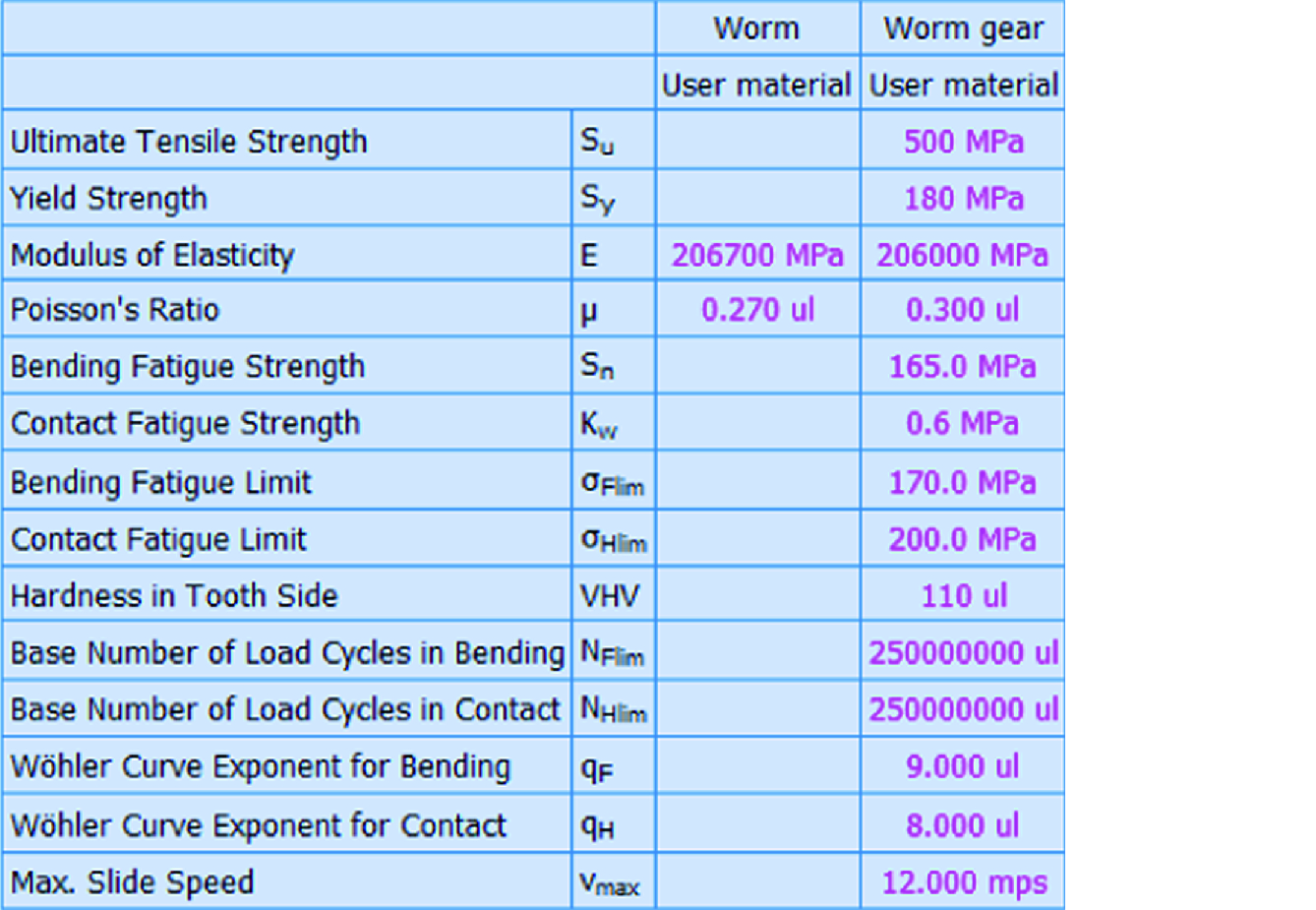
Simple defining of the new materials according ISO 6336-5 (ANSI/AGMA 2001-D04)

Complete calculation of tolerances in accordance with ISO 1328 (ANSI/AGMA 2015-1-A01) Design of gearing for exact axis distance. Calculation of strength parameters, safety check.
Autodesk inventor 2015 spur gear unit correction windows#
Optimization of toothing by use of proper correction (balancing specific slips, miminizing specific slips, strength.). Autodesk Integrations Overview SmartDesk A seamlessly integrated, affordable, out-of-the-box, Windows based drawing and document management tool for. Calculation of complete geometric parameters (including corrected toothing). Design for entered coefficients of safety (static, dynamic).

It worked fine, and produced results that were entirely satisfactory, to a point. Automatic design of a transmission with the minimum number of input requirements. Some of you may have followed the saga of the 8mm scanner I built, using an Arduino and a Canon IXUS95 with 3D printed parts. Select the spur gear, right-click to display the context menu and select the Edit Using Design Accelerator command. Calculation of helical and straight toothing. Open the Autodesk Inventor assembly with the already inserted Design Accelerator spur gear. Application is developed in MSĮxcel, is multi-language and supports Imperial and Metric units and solves the following main tasks: Geometric design and strength check of planetary gearing with straight and helical toothing.


 0 kommentar(er)
